The Circuit
Here we have the basic circuit for the hexapod. As you can see it is based on two standard IC chips, a 74HC14 and a 74HC86.
The
neat thing about using inverters in this way is that it takes your DC
signal and switches the out put from high to low, (positive to negative)
at an adjustable rate. For a regular DC motor, this translates to an
alternating left to right motion. The resistors and capacitors determine
the rate of the switching and duration of time the motor will be
turning a desired direction.
HISTORY:
I
will include this section to give credit to the original designers of
the circuit, and a bit about how it evolved. - More to come later
CIRCUIT LAYOUT:
The
circuit schematic above is shown in this way for "Freeform"
purposes. The pins are down with the view being above the chips, an
amateur therefore can see how the components solder together. The first
time I tried this, I used a blank PCB project board from Radio Shack
like THIS one:

...it was kind of messy and ended up looking like this:

For the
B.A.H.X. project, I decided to go ahead and have some PCBs made
professionally, since I wanted to explore this concept a bit with some
bigger and smaller projects. I am really satisfied with the results:
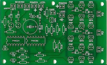
THE PCB's VARIATIONS on SCHEMATIC:
I included some variations on the original schematic for my PCB:
1. It has a seperate power source input
for the motor section. This is there in case I want to use motors
requiring more than 6V. More than 6V will burn out the ICs. However, If
I am using 6V or under, I have a jumper pin that connects the motors to
the IC power source.
2. Led indicator Outputs
- I've included a couple of ports to plug in LEDs in order to indicate
"power on", the second LED is to indicate the power for the secondary
power if there is one. (Resistors for the LEDs calculated and included
in the PCB.)
3. Motor Drivers (6 transistor H-Bridge)- Unless you are using very, very efficient motors,
the circuit will not put out enough power to run your gear motor. I've
included three 6-transistor H-bridges to boost the power. The 6 transistor H-bridge is an old tried and true method of building a home made motor driver, invented by Mark Tilden himself. However, I changed it up a bit by including diodes to prevent a burnout.
| 